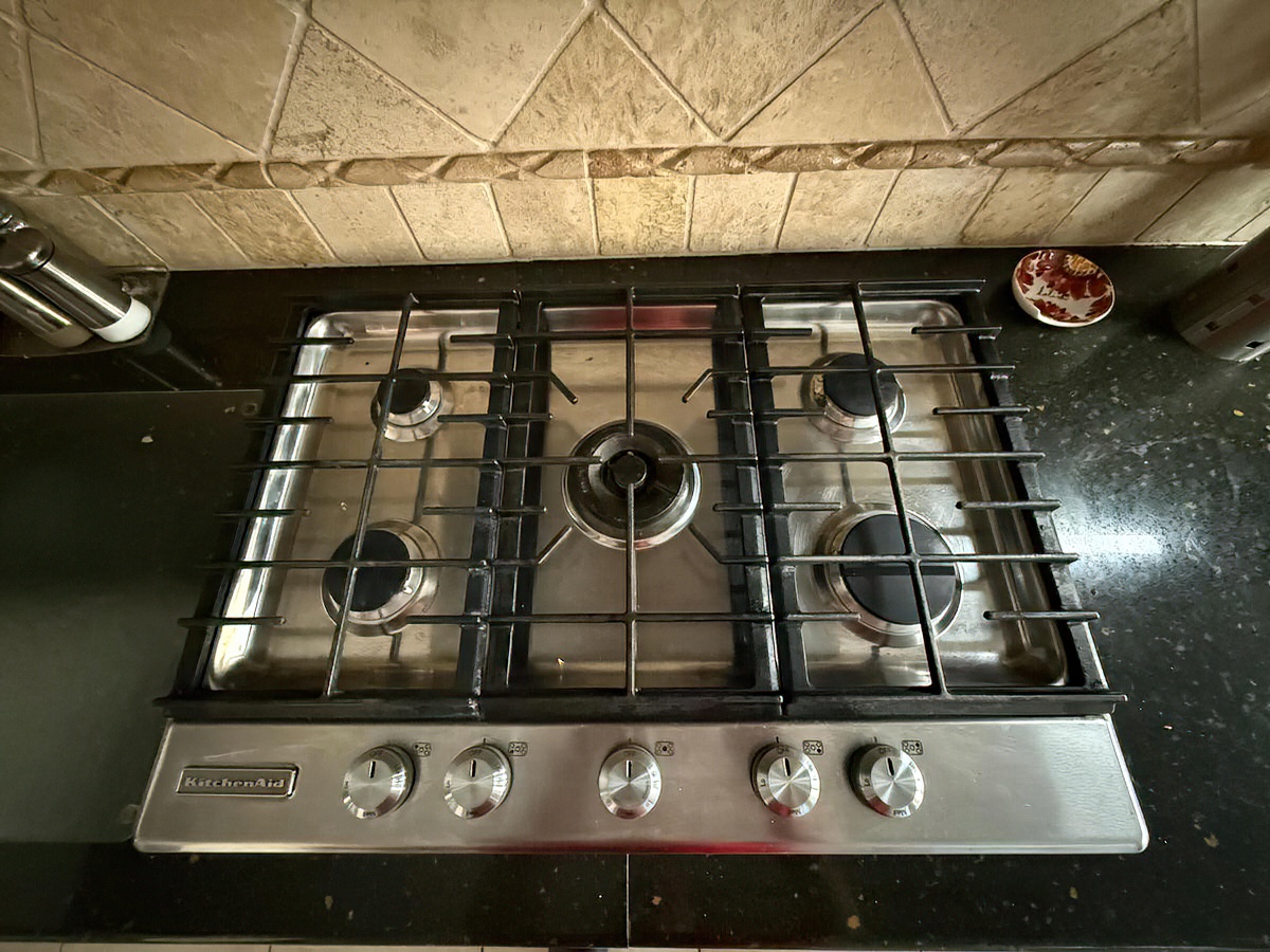
Kitchenaid Cooktop Saved From The Landfill
This article is about my perfectly good Kitchenaid cooktop, which was saved from the landfill. I have become increasingly critical about the enshitification of things that once were repairable. The list of things made shitier with time is nearly boundless. With few exceptions, almost anything manufactured in the last decade or two has been designed to fail within a short time and with little or no chance of fixing it. Manufacturers of anything electronic once provided a schematic in the back of the excellent manual or inside the chassis. Today, almost nobody provides any service documentation whatsoever. Manufacturers made spare parts available for reasonable periods of time, sometimes decades past the models sold.
Even High-end Appliances Now Throwaway
Today, most manufacturers obfuscate the components or etch off the standard identification before they are sold. It’s so annoying when you are trying to repair something that is still very useful.
The idea behind all of this is to ensure that your Refrigerator, Washer, Dryer, Vacuum Cleaner, Toaster, or Air Conditioner unit fails, and with no parts or information to fix it, causes you to discard the old and buy new. I HATE this. I hate the fact that just because HP or Epson decides to discontinue a printer model, I must throw mine away when something inside fails and buy another. It doesn’t print any better. But, because I cannot buy a new rubber roller for the paper feeder, my otherwise perfectly good printer is now junk. I reject this notion every chance I can. Many of us do. Today, I write of my latest act of rebellion against Kitchenaid, aka Whirlpool, aka private equity bullshit.
The Cooktop
The item in question is a high-quality stainless steel gas cooktop branded Kitchenaid but made by Whirlpool. This cooktop has performed flawlessly since 2007 and still looks great. The model KFGS306 is part of the Kitchenaid Architect II series. It cost about $1800.00 USD new.

The Issue and Symptoms
My wife had been using abnormally long pans across two burners simultaneously. These long pans were on medium heat for a long time as she was dyeing some stuff in the pans. The range hood was operating correctly and on high. Apparently, the temperature got high enough that it began to damage the rubber around the five burner knobs due to the close proximity of the heated pans.
Ok, lesson learned. We’ll go online and find some replacement knobs somewhere. Kelly found them somewhere online, but dang, they were $140.00 plus tax and shipping! Gulp. Ok, big lesson learned. Later that night, when it came time to prepare dinner, Kelly noticed that the burners weren’t igniting. Normally, there is a distinct tick tick tick for piezo electric spark igniters when you turn on a burner. The spark stops as soon as the burner ignites, resulting in a blue gas flame. Hmmm. Here’s when Kelly calls Kenny to take a look.
The Failure
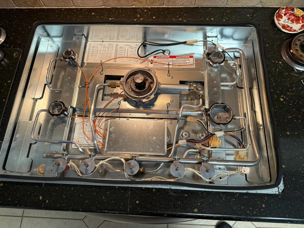
After dismantling the cooktop to expose the stuff underneath, I ignored the gas-related stuff and focused my attention on the electrical bits. It didn’t take long to get the lay of the land. I found the black and white pair of wires feeding the primary side of a transformer after I removed a protective shield. My multimeter confirmed that I had 120v AC into the transformer, so I knew we didn’t blow a circuit breaker or fuse to this point. Moving on.
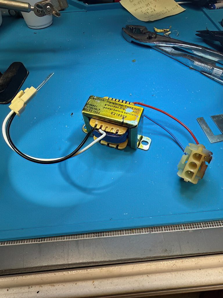
The secondary wires from the transformer fed into a Molex connector that led to a blue plastic box called a spark igniter module. Testing the secondary wires revealed no voltage coming from the transformer at all. So, the transformer was an open circuit on the secondary side. Bummer. Now, we need to identify the source for a replacement transformer, and the part number was conveniently printed on top of the faulty one.
The Faulty Transformer
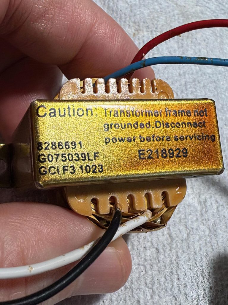
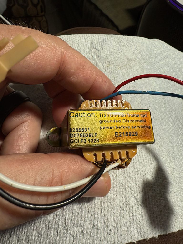
It turns out the faulty transformer, part number WP828691, is a whirlpool isolation transformer. Isolation transformers are used to prevent a direct coupling with the AC Mains in the event of a short circuit failure. They are purely for safety, but that’s a good thing. I need to keep this transformer in the cooktop. The trouble is this transformer is not available anywhere and is not reputable. This means this transformer, which sold for about $23.00 new, is now nowhere to be found. Unobtanium. So, unless we get used to using lighters or matches to light our burners, I need to figure something out or throw my otherwise perfect gas cooktop away and fork over another couple of grand for a replacement cooktop. This is bullshit!
I’m So Pissed Off I Decided To Fix The Transformer
How hard can it be, right? LOL Later that night, I ventured into the unknown and began disassembling the power transformer after searching the Internet and electronics part houses for an equivalent replacement. Having found none, I went all in. As luck would have it, this transformer was a well-made little sucker. And, I figured if I couldn’t get through the repair without damaging the unit, the worst-case scenario was I’d have to buy a new cooktop.
Disassembly Of The Power Transformer
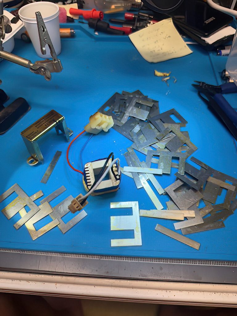
After committing to taking periodic photos with my phone along the way, I began at the bottom or underside of the transformer by folding back the four tabs holding the metal shield over the E-Plates. A small pair of side cutters made short work of folding the tabs. The next part was more challenging: finding a way to separate the first E plate from the stack and pull it out. I’m not going to lie. This is a fiddly bit and requires quite a lot of patience. Forceful care is required to avoid damaging the plastic core and bending one or more E-plates.
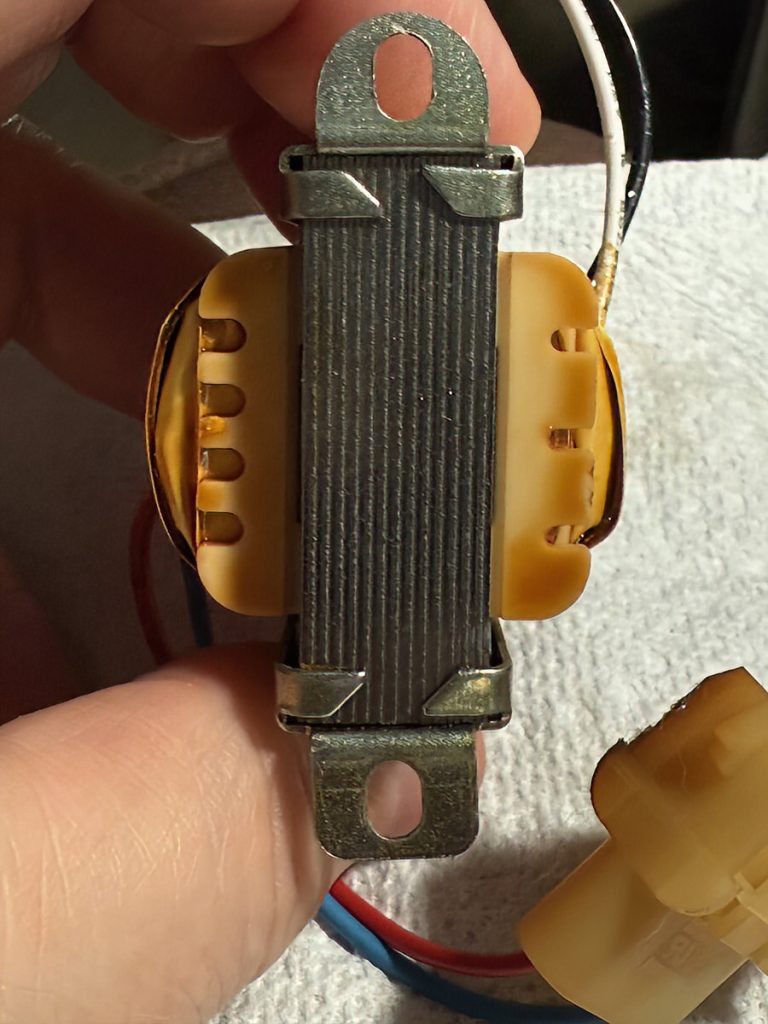
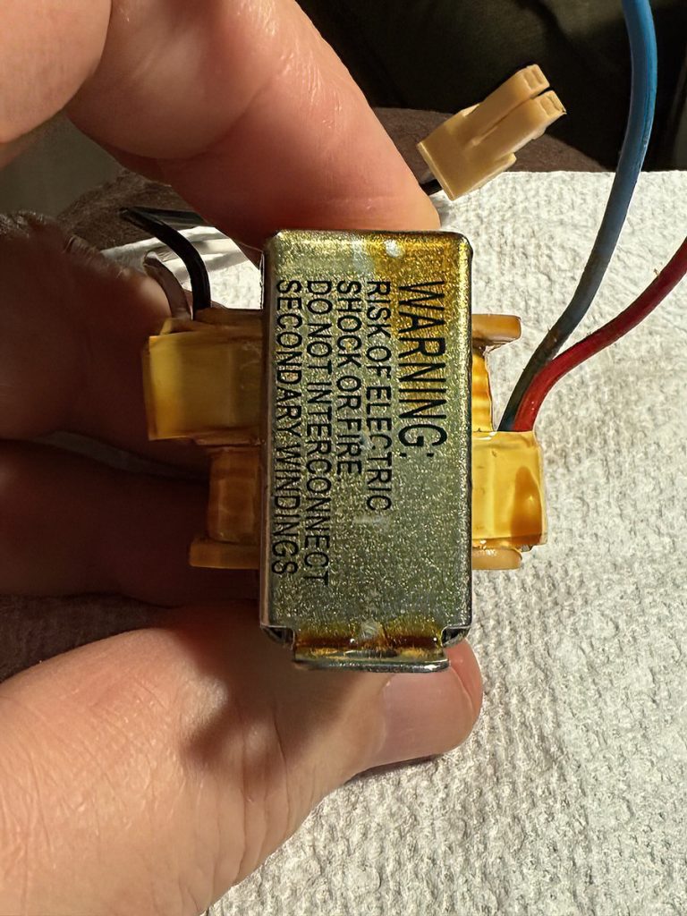
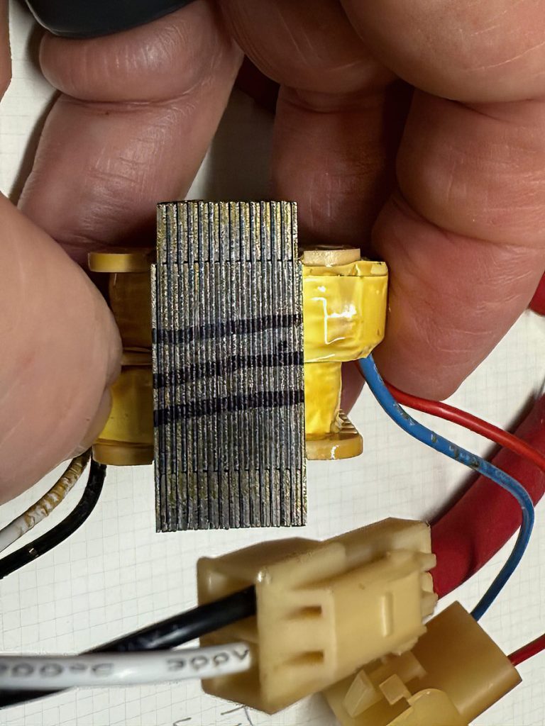
E-Plates & Spacers Removal
Separating the first E-plate from the rest is no simple task, but once removed, the second will be easier, the third even easier, etc. The transformer has a varnish-like coating that definitely makes disassembly tougher, but ultimately, I was able to remove all the E-plates and the spacers.
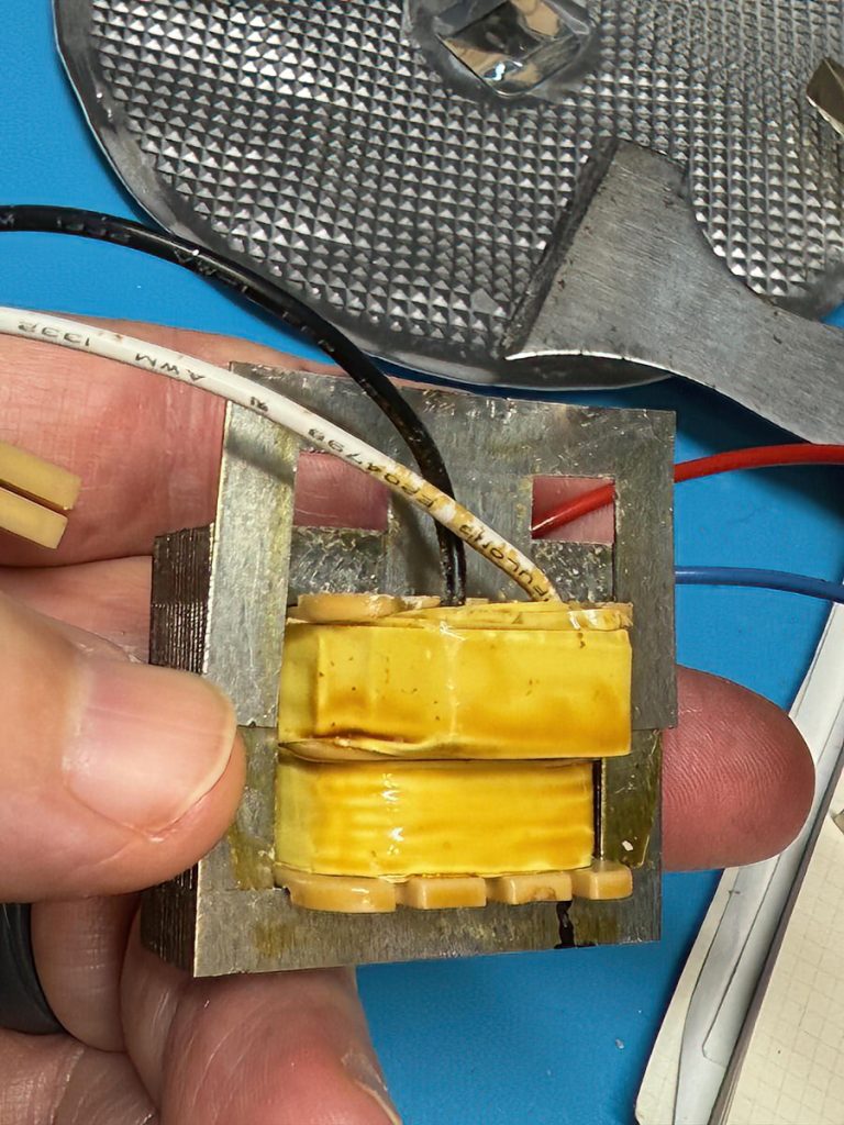
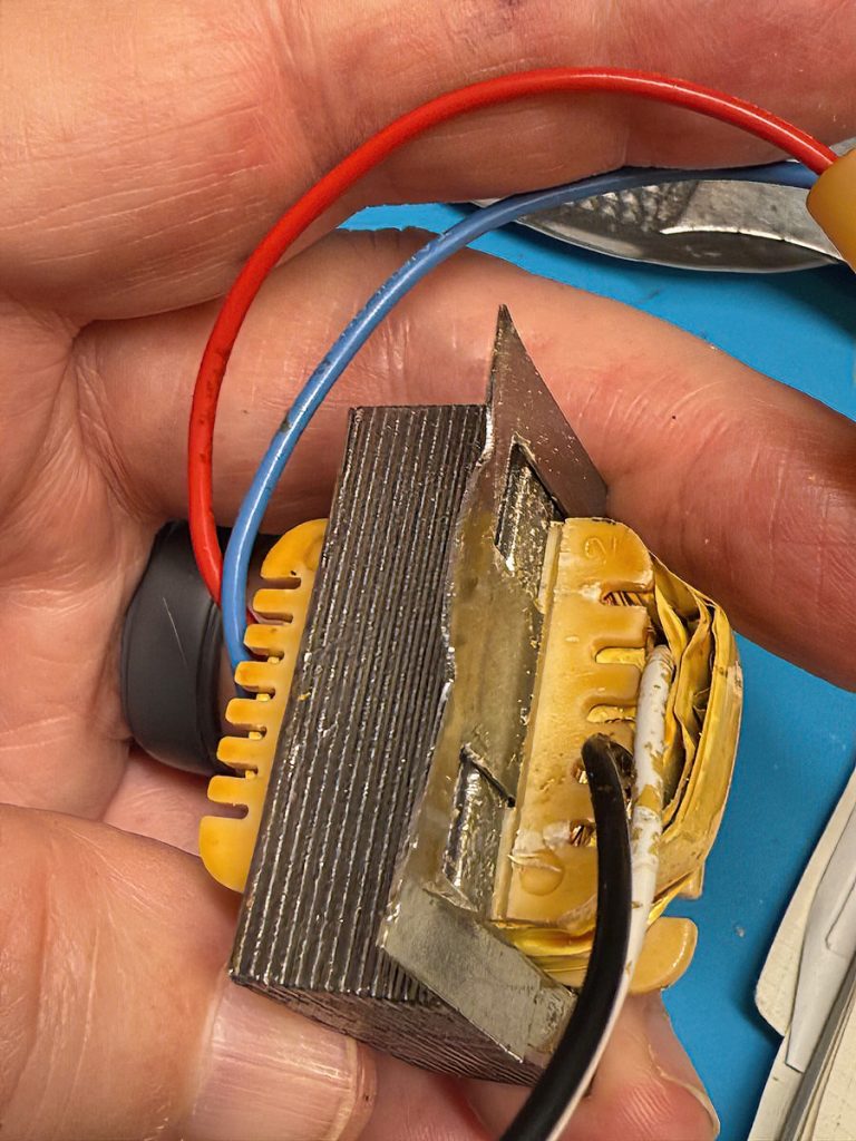
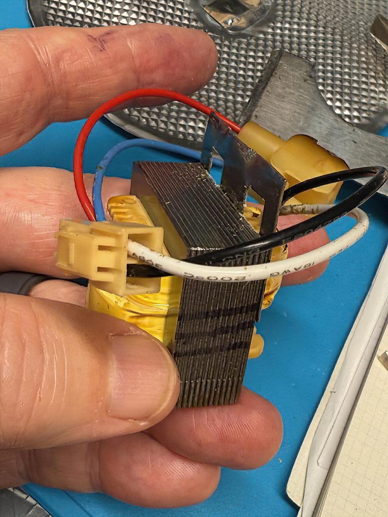
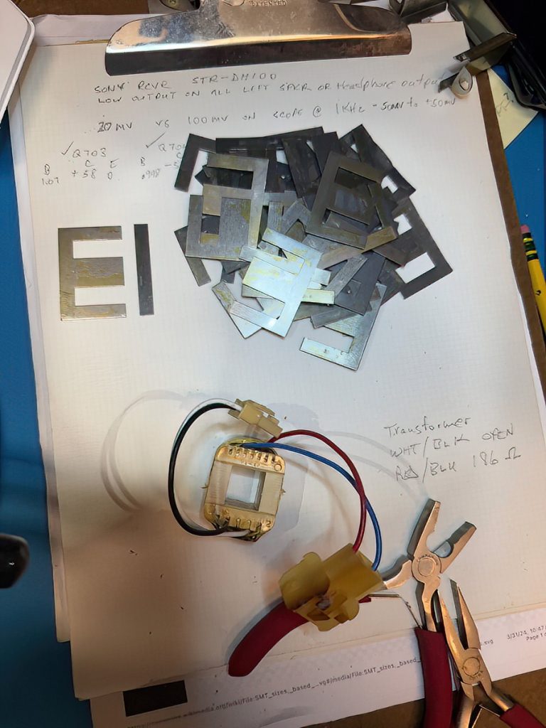
The Core Windings
Once all the E-plates and spacers are removed, the core of this isolation transformer is exposed, which means two distinct and separate windings. Since the Primary Winding was good, with low resistance across the wires, I focused on the secondary winding. Again, the secondary measured open circuit or no connection between the two wires. There is no need to mess with the primary, so we’ll leave it alone.
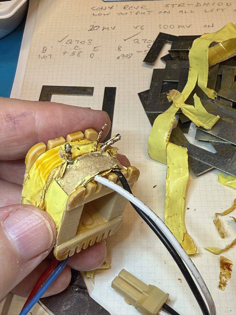
Removing The Tape Carefully!
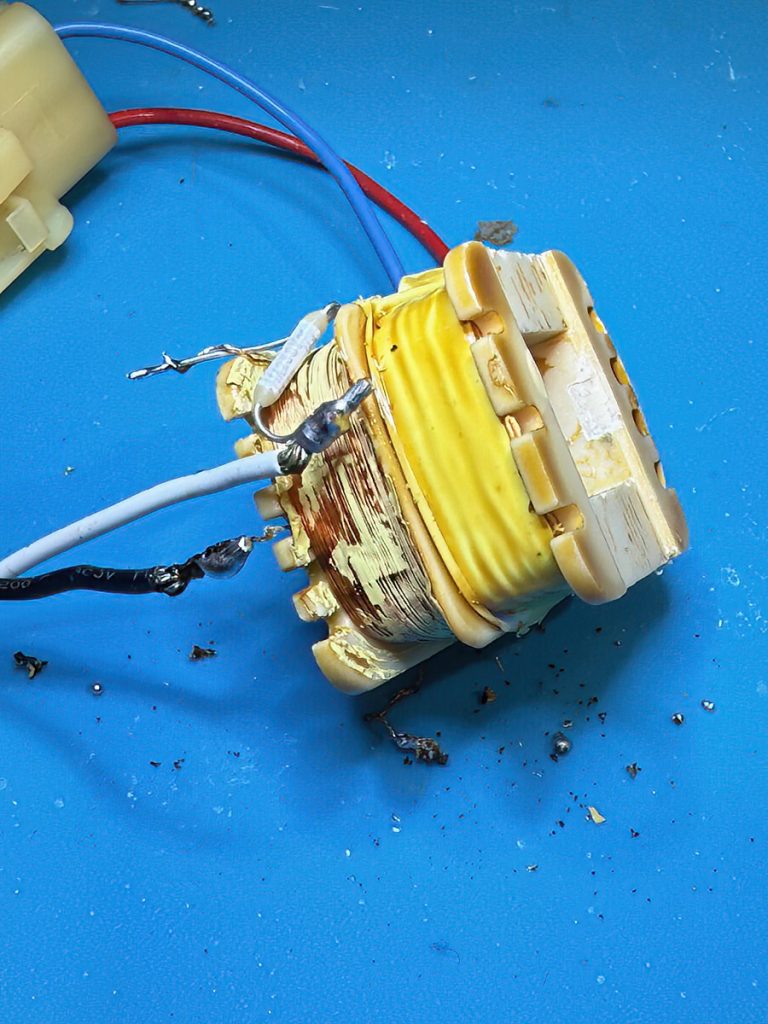
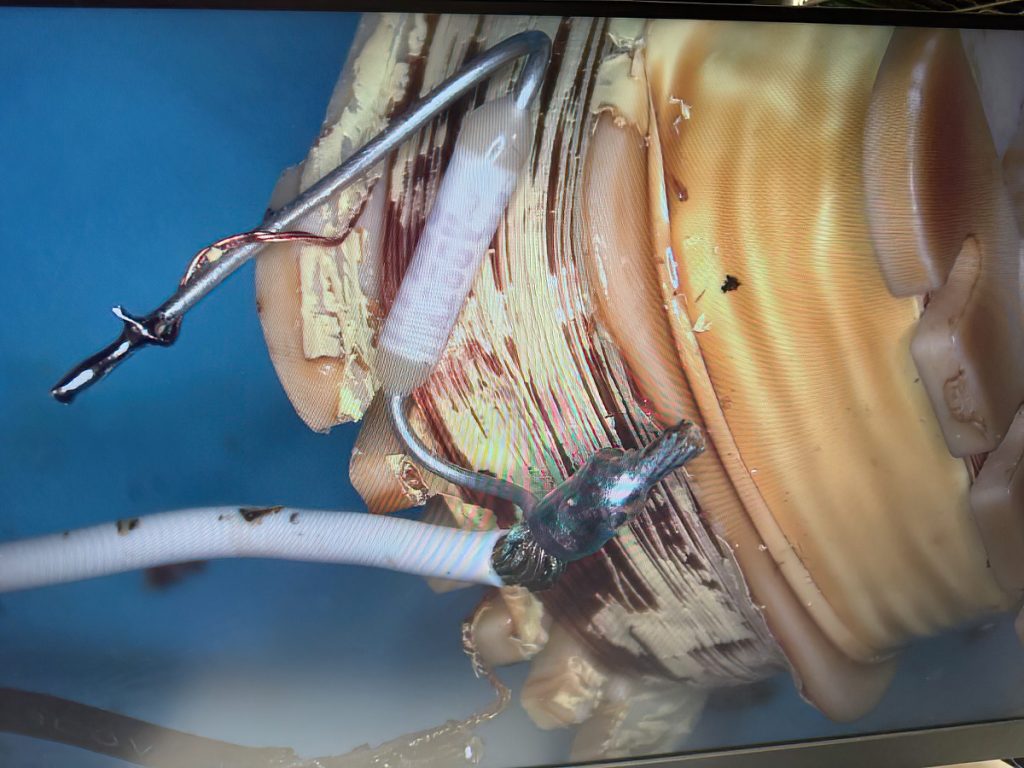
I began to remove the super thin, non-conductive mylar tape from the secondary winding of the core. Using tweezers, I slowly and methodically peeled back and unwound more tape. After a wrap or two, I came across a stiff cardboard piece covering the first of several soldered joints. Unwinding more tape, I came across another cardboard spacer and removed it. Now I could see the tiny enameled copper wire ends soldered to a tiny component in series with one side of the coil. After one more unwrapping of tape, I exposed the other end of the coil soldered to a much larger stranded wire. The soldered connections looked good on both tiny wire ends. The soldered connection to the mystery component was also good. What was the tiny component?
The Mystery Component That Failed: A Temperature Fuse
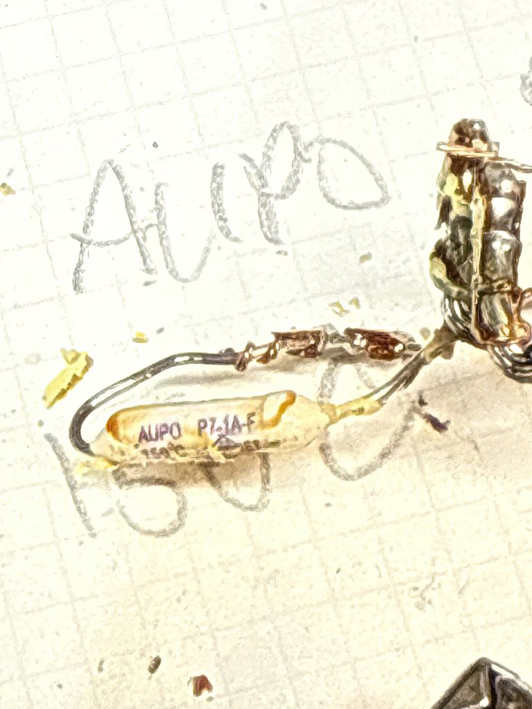
I’ve known about fuses sometimes embedded in transformer windings for years, but for some reason, I had not considered that possibility in this 1:1 120v isolation transformer. Yet, once under the microscope, clear as day, it was a 1A 150C fuse. And, more importantly, it was blown. After de-soldering it from the winding core, I measured the winding and found it to match the primary side. Woo-hoo, the winding was good. No shorts.
Now, to find a replacement fuse. Within a few days, I could order a replacement for a few bucks, actually, ten fuses for $6.99, to be exact. So, to summarize, this little fuse is designed to break the circuit inside the transformer if the current exceeds 1 Amp or if the temperature within the transformer exceeds 150 degrees C (302 degrees F). In our case, ours failed when the temperature exceeded 302F. The cause has been identified; now it’s time to put it back together and see if anything else is broken.
Replacing The Fuse And Transformer Reassembly
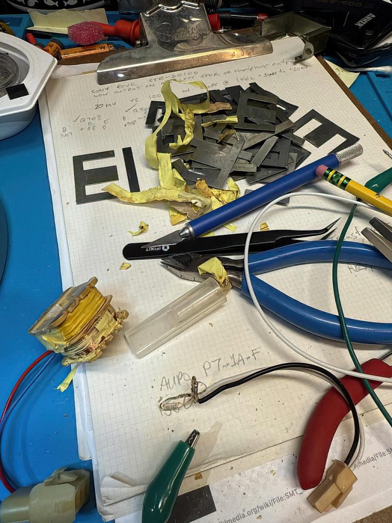
I cannot stress enough how fragile the tiny enameled transformer wires are. It is important to avoid scratching or damaging the enamel coating to avoid short circuits. The task now is to solder the replacement fuse, which is about the size of a 1/4-watt resistor for your electronic types, in series between one end of the secondary coil winding and one of the 16 ga wires. The other 16 ga wire is soldered directly to the other end of the winding.
To accomplish this, you must remove some of the enamel coating from the ends of the winding wires and pre-tin them with solder. It’s delicate, and a set of “helping hands” is handy for keeping things in place as you work. It’s a bit like a game of Tetris trying to bend and contort the fuse and wires carefully without damaging them or allowing them to touch a short circuit.
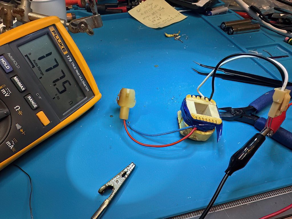
You quickly realize the value of those little pieces of cardboard. I tried to find yellow mylar tape but had to settle for blue 10mm wide, so I used blue to close it all up. It took a couple of tries to get things to fit without problems, so patience is a virtue. The tape finally stayed put long enough for me to get a second wrap and the second winding connection in place and aim in the right direction. After a few more wraps, I inspected and measured, and the secondary measured almost exactly the same as the primary, within one Ohm. Excellent!
Reassembling The E-plates
With the windings both measuring fine, re-inserting all of the E-plates begins. The plates are all exactly the same except for the first and second ones that I yanked out and bent up a little in the process. So, the tedious process of inserting one at a time, alternating from one side of the core to the other 180 degrees until things get real tight. Now, you’re down to the last three or four E-plates. It’s tricky to squeeze and pack them into place.
In the end, you may not be able to get the last one or two in without damaging the core. Stop! It’s okay. If you cannot get the last one or two plates back in without undue force, leave them out. It’s ok. The effect will be negligible. After the E-Plates are installed, the spacers are inserted on each open end of the E-plates. After you get all the spacers in place, it’s time to put the shield cover back on and fold the tabs down on the underside of the transformer. You’re done. Congrats. Measure it again to ensure there are no shorts to the case from any of the wires. Also, check for a low resistance continuity between each side of the transformer. If all is good, put that cooktop back together!
Cooktop Fixed Before Thanksgiving!
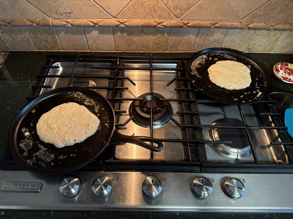
I’m more than pleased that I could save this excellent appliance from the landfill. Once I plugged everything back and reinstalled the cover, it worked perfectly. I wouldn’t be surprised if it lives on for at least twenty more years. Was it worth it? To me, it was. It’s the principle of the whole thing to me. I had the time and felt I had the skills and tools to go for it. So, yeah, it was worth it. If anything else fails on or in this cooktop, whether it’s the gas valves or sensors, switches, igniters, or the igniter circuit board, you can bet your bottom dollar I will try my best to fix it and save it from the landfill again. K

